Design Considerations
Contents
Let’s discuss some of the design considerations for Cross-VDC Networking inside of vCD. It is important to note that although Native NSX supports up to 16 sites (or 16 vCenters), vCD 9.5 as of today supports up to four (4) sites only.
Below are applicable considerations pulled from the NSX Cross VC Design Guide.
When deploying a Cross-VC NSX solution across sites, the requirements for interconnectivity between two sites are:
- IP Connectivity (Layer 3 is acceptable)
- 1600+ MTU for the VXLAN overlay
- < 150 ms RTT latency
In addition, it’s important to note, since logical networking is spanning multiple vCenter domains, there must be a common Administrative Domain for both vCenter domains/sites.
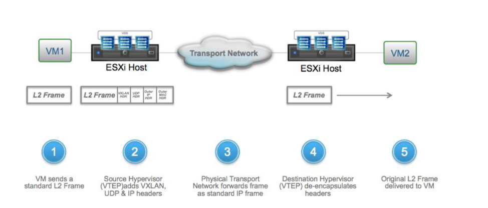
The physical network can be any L2/L3 fabric supporting a 1600-byte MTU or greater. The physical network becomes the underlay transport for logical networking and forwards packets across VTEP endpoints. The physical environment is unaware of the logical networks or VXLAN encapsulation as shown in Figure below. Encapsulation/de-encapsulation of the VXLAN header is done by the VTEPs on respective ESXi hosts, but the physical network must support the 1600 MTU to be able to transport the VXLAN encapsulated frames.

Typically, L2/L3 over dedicated fiber or a shared medium like MPLS service from an ISP is used for connectivity between sites with L3 connectivity being preferred for scalability and to avoid common layer 2 issues such as propagation of broadcast traffic over the DCI (data center interconnect) link or STP (spanning tree protocol) convergence issues.
Once the NSX Manager at Site-A is deployed via standard NSX Manager installation procedures (NSX Manager is deployed as an OVF file), it can be promoted to primary role.
Once the primary NSX Manager, is configured, the Universal Control Cluster (UCC) can be deployed from the Primary NSX Manager. Similar to standard design guide recommendations for resiliency, the NSX controllers should be deployed on separate physical hosts; anti-affinity rules can be leveraged to assure multiple NSX controllers don’t end up on the same physical host. If NSX controllers are deployed on the same host, resiliency is lost because a physical host failure can bring down more than one controller or possibly even the entire controller cluster if all controllers are on the same host.
The controllers distribute the forwarding paths to the vSphere hosts and have complete separation from the data plane. If one controller is lost, UCC will keep functioning normally. If two controllers are lost, the one remaining controller will go into read-only mode and new control plane information will not be learned but data will keep forwarding.
If the entire controller cluster is lost, again, the data plane will keep functioning. Forwarding path information on the vSphere hosts do not expire, however, no new information can be learned until at least two controllers are recovered.
We can work around this by enabling the Controller Disconnected Operation (CDO) mode. Controller Disconnected Operation (CDO) mode ensures that the data plane connectivity is unaffected in a multi-site environment, when the primary site loses connectivity. You can enable the CDO mode on the secondary site to avoid temporary connectivity issues related to the data plane, when the primary site is down or not reachable. You can also enable the CDO mode on the primary site for the control plane failure.
CDO mode avoids the connectivity issues during the following failure scenarios:
- The complete primary site of a cross-vCenter NSX environment is down
- WAN is down
- Control plane failure
- The CDO mode is disabled by default
When the CDO mode is enabled and host detects a control plane failure, the host waits for the configured time period and then enters the CDO mode. You can configure the time period for which you want the host to wait before entering the CDO mode. By default, the wait time is five minutes.
NSX Manager creates a special CDO logical switch (4999) on the controller. The VXLAN Network Identifier (VNI) of the special CDO logical switch is unique from all other logical switches.
When the CDO mode is enabled, one controller in the cluster is responsible for collecting all the VTEP information reported from all transport nodes and replicating the updated VTEP information to all other transport nodes. After detecting the CDO mode, broadcast packets like ARP/GARP and RARP is sent to the global VTEP list. This allows to vMotion the VMs across the vCenter Servers without any data plane connectivity issues.
Universal Control VM Deployment and Placement
The Universal Control VM is the control plane for the UDLR. Similar to the DLR Control VM in non-Cross-VC NSX deployments the Universal Control VM will be deployed on the Edge cluster and will peer with the NSX Edge appliances. Since Universal Control VMs are local to the vCenter inventory, NSX Control VM HA does not occur across vCenter domains. If deployed in HA mode, the active and standby Control VM must be deployed within the same vCenter domain. There is no failover or vMotion of Universal Control VMs to another vCenter domain. The Control VMs are local to the respective vCenter domain.
A deployment that does not have Local Egress enabled will have only one Universal Control VM for a UDLR. If there are multiple NSX Manager domain/sites, the Control VM will sit only at one site, which will be the primary site and peer with all ESGs across all sites.
In Active/Standby vCD Deployment (Tenant Layer in our case) and upon Active site failure, the Provider will need to manually redeploy the Tenant UDLR Control VM on the Standby (now Active) site. Promoting the Secondary site to active is a pre-requisite that the Provider will have to do upon total Primary site Failure.
A multi-site multi-vCenter deployment that has Local Egress enabled (In our case the Provider Layer) will have multiple Universal Control VMs for a UDLR – one for each respective NSX Manager domain/site; this enables site-specific North/South egress. If there are multiple NSX Manager domain/sites, there will be a Control VM at each site; each control VM will also connect to a different transit logical network peering with the ESGs local only to its site. Upon site failure, no Control VM needs to be manually redeployed at a new primary site, because each site already has a Control VM deployed.
Stateful Services

In an Active/Passive North-South deployment model across two sites, it’s possible to deploy ESG in HA mode within one site where ESG is running stateful services like firewall and load balancer. However, HA is not deployed across sites.
The stateful services need to be manually replicated at each site, this is an important consideration. This can be automated via custom scripts leveraging NSX REST API. The network services are local to each site within both the Active/Passive North/South egress model and the Active/Active North/South egress model.
Graceful Restart
One item to note is Graceful Restart is enabled on ESGs by default during deployment. In a multi-site environment when using ESGs in ECMP mode, this typically should be disabled.
If it’s left at the default and aggressive timers are set for BGP, the ESG will have traffic loss on failover in an ECMP environment due to preserved forwarding state by graceful restart. In this case, even if BGP timers are set to 1:3 seconds for keepalive/hold timers, the failover can take longer. The only scenario where Graceful Restart may be desired on ESG in an ECMP environment is when ESG needs to act as GR Helper for a physical top of rack (ToR) switches that is Graceful Restart capable. Graceful Restart is more utilized in chassis architecture which have dual route processor modules and less so on ToR switches.
Final Cross-VDC Considerations
While Cross-VDC networking presents many new networking capabilities, there are a few things we’ve learned that are not covered as of today. These are important factors to consider when deploying Cross-VDC for your tenants.
- Universal Distributed Firewall (UDFW) is not a concept available via vCloud Director 9.5. Any DFW rules will need to be created on a per orgVDC site and managed independently.
- Network services within respective OrgVDC Edges will need to be managed independently. Therefore, a NAT rule that is on Site-A does not propagate to Site-B – this is an important factor to consider during failover scenarios.
- Proper thought needs to be put into ingress of traffic between multiple sites. Consider using a Global Load Balancer (GLB) technology to manage availability between sites.
- As expected, Cross-VDC networking only works with NSX-V. NSX-T has a different interpretation of multi-site capability and this is something we are investigating for future vCD releases.
Conclusion
While this is blog series covered many aspects of Cross-VDC networking within vCloud Director, this is just scratching the surface of design considerations, use case discussion, and feature sets available inside of vCloud Director.
If you have interest in learning more or discussing a potential design, please reach out to your VMware Cloud Provider field team. Thanks again for reviewing our material!
Daniel, Abhinav, and Wissam


