In this blog series, we will be covering several aspects of Cross-VDC Networking inside of VMware vCloud Director 9.5. This was created by Daniel Paluszek, Abhinav Mishra, and Wissam Mahmassani.
This blog covers the following:
- Overview of the High-Level Design
- Failure Scenarios
Overview
Contents
The goal of this high-level design is to provide optimal availability of network services from the Provider and Tenant layer. We must adhere to Cross-vCenter NSX best practices, so do note that we are presuming you are aware with these guidance parameters.
In this suggested design, we have two layers of NSX:
- Tenant layer within vCloud Director
- Provider Managed layer
The goal is to provide high availability between the two sites while meeting the stated requirements of Cross-VDC networking.
While the Tenant layer is auto-provisioned by vCloud Director, the Provider Managed layer will be initially set up and managed natively in NSX inside of the resource/payload vCenters.
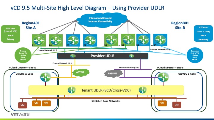
Within the Tenant layer, this is controlled and managed by vCD and provides the spanning of L2 tenant (orgVDC) networks across the member sites by stretching the created Universal Logical Switch. The Tenant Universal Distributed Logical Router (UDLR) will be provisioned by vCD during creation of a VDC Group and will take care of the required routing for the different tenant networks. The tenant Edge Services Gateway (ESG) will terminate all tenant services such as NAT, Edge Firewall, DHCP, VPN, Load Balancing and will be the North/South ingress/egress point for workloads managed by the vCloud Director organization.
In this high-level design, we are deploying the Tenant UDLR with egress points that are in Active/Standby (passive) mode where all Tenant A’s (Coke) workload traffic will egress from a specific Edge. In this example, we will egress from Site-A –
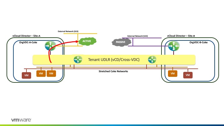
The rationale behind Active/Standby mode is to maintain stateful services that are running on the tenant’s ESG and explicit control of the ingress traffic which will also assist in any failure considerations.
Since vCloud Director provides secure and isolated multi-tenancy, we can provide a design on a per Organization (tenant) basis. For example, I could have Tenant B (Pepsi) that has their egress set at Site-B –
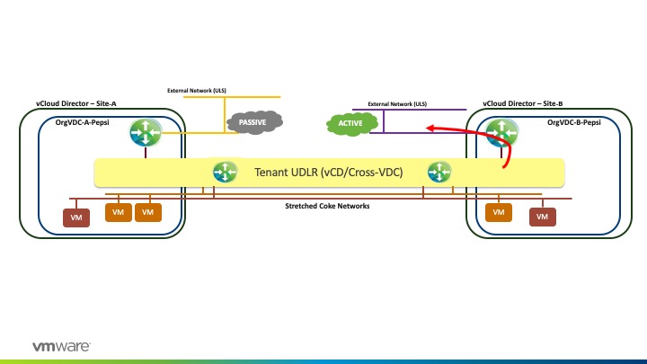
Therefore, this allows the Provider to manage tenant traffic and distribute the network utilization across sites.
Now, let’s discussed the Provider Managed layer, which is initially established by the Provider and manage in native NSX terms outside of vCloud Director.
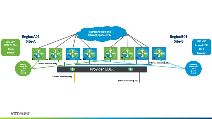
Each Tenant Edge (<OrgName>-<OrgVDC>-Edge) will peer externally with a pre-provisioned UDLR. This uplink transit interface will be on the VXLAN overlay, or in other words just a Universal Logical Switch that’s presented to vCloud Director as an External Network. With this configuration, a Provider could scale to up to 1,000 tenants as a DLR supports up to 1,000 logical interfaces (LIFs).
In this high-level design, we will be utilizing an Active/Active state with local egress mode at the Provider Layer (Provider UDLR). Therefore, local traffic will egress at its respective local site. With this configuration, a UDLR Control VM will be deployed on each site.
While utilizing an Active/Active configuration, we would also pair this with ECMP on the Provider UDLR (P-UDLR) and Peer with up to 8 Provider Managed Edges spread equally between the two sites. Therefore, we would have E1, E2, E3, and so on until E8 for each site. In summary, we would have the following:
- Site-A
- Provider Control VM will peer with ESGs 1-4 (Green) on Site-A while peering with ESGs 5-8 on Site-B.
- This is possible as E1-E8 reside on the same Universal Logical Switch.
- E1-E4 will have a higher BGP weight peering with the Provider-UDLR for any oVDC network routes while E5-E8 will have a lower BGP weight.
- Site-B
- This will be very similar to Site-A as we will be splitting up ESG’s between the two sites.
The Provider UDLR will reach the Tenant’s Edges uplinks via direct-connected routes. This is where Public IP’s will be floating and hence, Provider UDLR will advertise direct-connected routes to the Provider Edges northbound.
For high availability purposes, the default originate would be advertised to all Provider ESG’s via the upstream physical network while BGP weights prefer the respective local site (for Coke, Site-A, and for Pepsi, Site-B).
Therefore, if we have a physical network failure on Site-A, the local provider edges will withdraw the routes (default originate) being advertised and traffic will then exit from Site-B physical infrastructure via the E4 to E8 Green (since this is the secondary BGP path). Similarly, traffic for site 2 will follow the same path but with Blue ESGs in charge.
Failure Scenarios
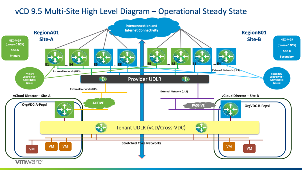
In this section, we will be reviewing the vCD NSX design that we are proposing. This focus will be around the packet life around failure considerations and how high availability also plays into these situations.
Scenario 1: Operational Steady State
Pepsi workloads will have their respective Tenant UDLR as their default gateway.
East/West Traffic:
Pepsi workloads that are communicating L2 East/West whether in the same in a single vCD instance, or across vCD sites, will utilize the stretched L2 universal logical switch and communicate successfully via Host VTEP encapsulation. If it is an Layer 3 / routed communication between workloads, then Tenant UDLR will do the routing on the source host and encapsulate the packet again via the VTEP to the destined workload via its host VTEP.
North/South Traffic:
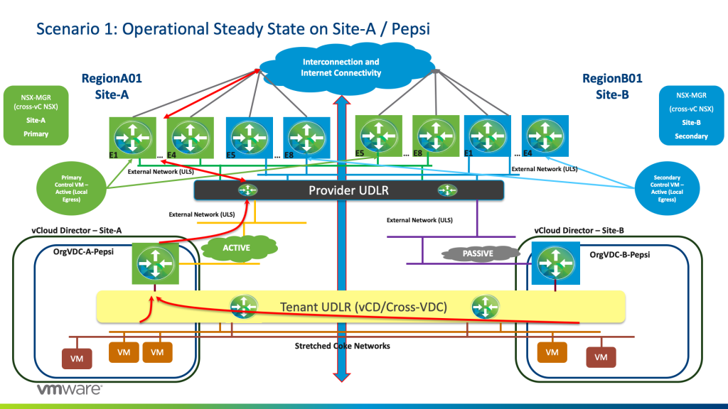
Traffic originating from Pepsi workloads whether they live on orgVDC Site-A and/or orgVDC Site-B will egress from the Active orgVDC-A-Pepsi Edge Services Gateway. Tenant UDLR has a BGP Configuration with 2 BGP Neighbours: one with the Active Tenant ESG, and another with the Standby Tenant-EDGE, with a higher weight for the Active Tenant-ESG/.
From the Active Tenant-ESG, traffic will egress to the Provider ECMP ESGs (E1 to E4 Green) due to the fact that the Provider UDLR has local egress (Active/Active) being configured in the Provider NSX layer.
The Provider Primary UDLR Control VM is peering BGP for oVDC routes with ECMP E1 to E4 Green on Site-A with weight 60 whereas with BGP weight 30 with ECMP E5 to E8 Green on Site-B.
The Provider Secondary UDLR Control VM is peering BGP for oVDC routes with ECMP E1 to E4 Blue on Site-B with weight 60 whereas with BGP weight 30 with ECMP E5 to E8 Blue on Site-A.
This is shown as highlighted in the diagram below for Tenant Pepsi that has an active Tenant-ESG on Site-A and passive Tenant-ESG on Site-B.
For tenant Coke, it has an active Tenant ESG on site 2 and a passive Tenant ESG on Site-A. Hence traffic will egress from Site-B Provider ESGs (E1 to E4 Blue) again due to the fact of local Egress being configured at the Provider NSX layer. See the diagram below –
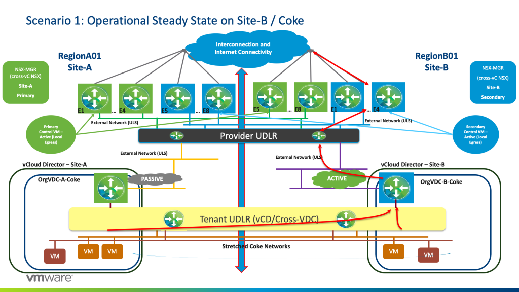
Note that due to the active/passive mode on the Tenant Layer, we maintained the stateful services that the Tenant ESG provisions such as NATing, firewall services, and so forth.
Always remember that the UDLR control VM is not in the data path as the UDLR is an instance present within the kernel on each vSphere host.
Moreover, notice how we distributed traffic to both sites for optimal efficiency of resources.
Scenario 2: Loss of Tenant’s Active ESG
In this scenario, let’s say we lose the Active ESG on Site-A for Pepsi.
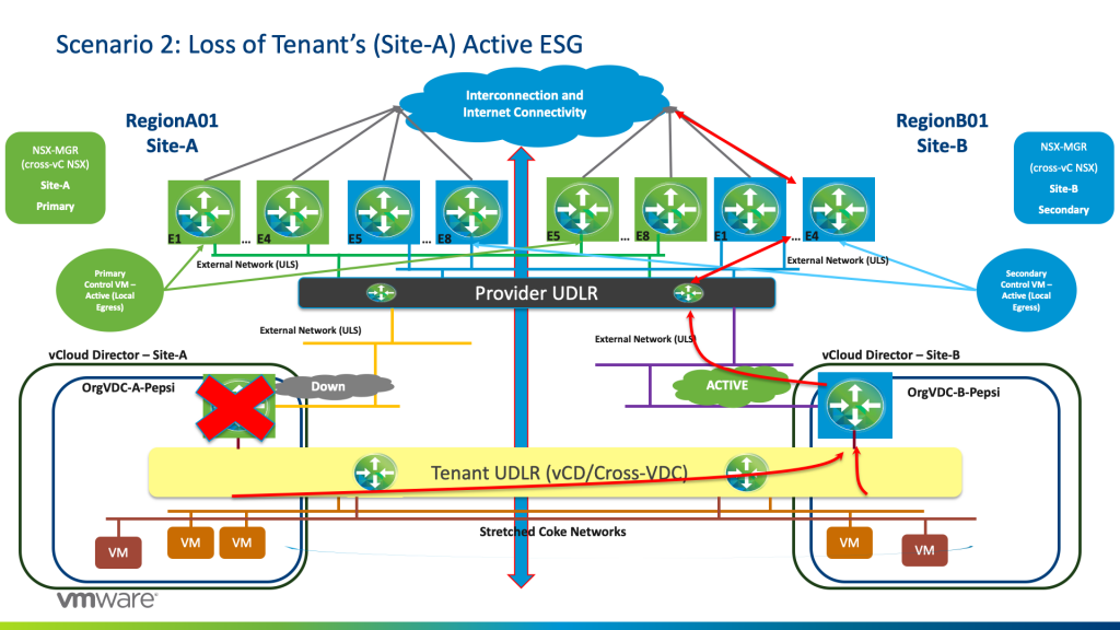
BGP weight kicks in as now the previously “Standby” ESG will become active and hence traffic will egress from the Tenant-ESG on Site-B (OrgVDC-B-Pepsi) and hence traffic will egress from E1 to E4 Blue.
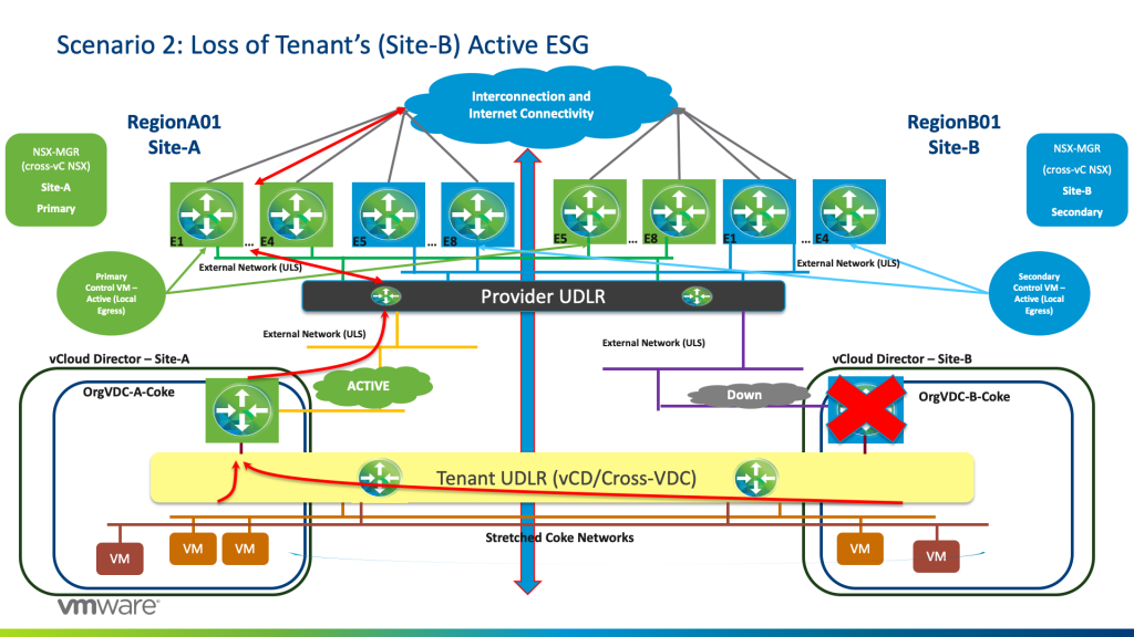
The same above scenario will happen with Tenant-Coke if Coke loses its Active ESG on Site-B.
Scenario 3: Loss of upstream physical switching on Site-A
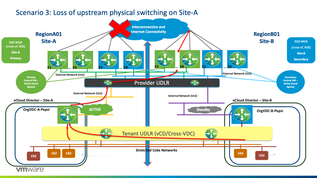
If we lose the physical core upstream, or technically the default originate, traffic will still egress from Active Tenant ESG on Site-A and the Provider UDLR will send the traffic to egress from E5 to E8 Green on Site-B as now and due to BGP weights kicking in, default originate is coming from those Edges on Site-B. Hence all internet traffic will be accessible from Site-B.
Coke traffic (who has their active Tenant-ESG on Site-B) are egressing normally from on E1 to E4 Blue on Site-B (refer to Scenario 1).
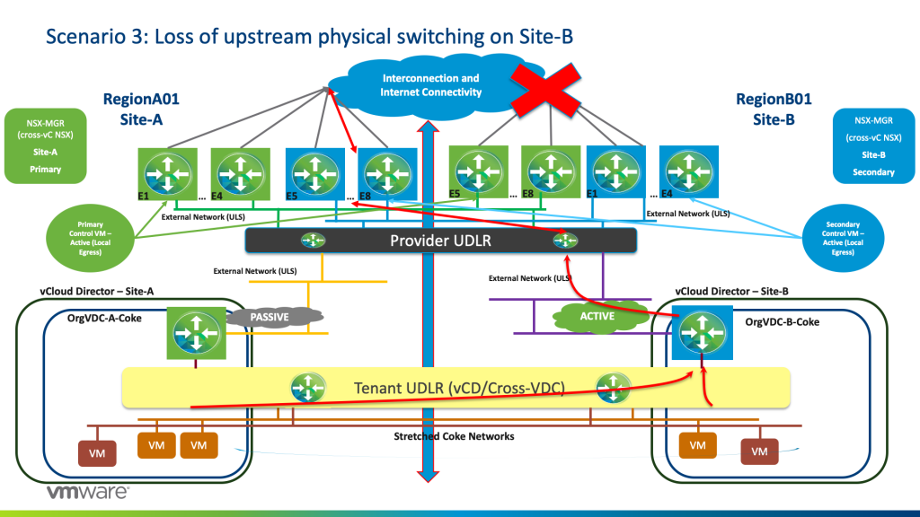
We would have the same expected result if I lose Internet connectivity on Site-B where now traffic for active Tenant-ESGs on Site-B will egress from the E5 to E8 Blue while Active Tenant ESGs on Site-A will still egress from E1 to E4 Green.
Up next – design considerations for Cross-VDC networking and conclusion to this series.

